Installation of Capillary Column (Graphite Ferrule)
Video (Installation of Graphite Ferrule to Column)
Video (Installation of Column to GC)
Required devices
No. |
Parts name |
Category |
Required number |
Note |
|---|---|---|---|---|
① |
10x12 Spanner |
1 |
||
② |
6x8 Spanner |
2 |
||
③ |
Tweezers |
1 |
||
④ |
Cutter, Capillary Tube |
1 |
||
⑤ |
Non Slit Nut |
1 |
||
⑥ |
Slit Nut |
1 |
||
⑦ |
Graphite Ferrule |
2 |
||
⑧ |
Graphite jig (INJ) |
1 |
||
⑨ |
Graphite jig (DET) |
1 |
A graphite ferrule that matches the inner diameter of the column must be selected.
Refer to
Ferrule Type
.
Note that this procedure cannot be used for GCMS.
Procedures
Step 1
Stop the instrument. Then, on the instrument monitor or workstation, check that the temperature of the column oven is lower than 40 °C, check that the temperatures of the injection port and detector are 50 °C or lower, and check that the gas supply is stopped and there is no residual pressure.
Step 2
Slide the injection port side of the column through the column nut (without slit) (⑤), and then through the graphite ferrule (⑦).
Organic matter easily adheres to graphite. If you directly touch graphte ferrule, it may affect the analytical data.
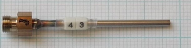
Step 3
Fix the graphite ferrule temporarily with the Graphite jig (⑧) and a 6×8 spanner (②).
In this case, push out capillary column about 10 mm from the Graphite jig.
-
When using Graphite jig for SPL/PTV, the sealed end of the graphite ferule is fixed at 34 mm from the column end.
-
When performing splitless analysis using a wide bore column with an inner diameter of 0.53 mm, use the Graphite jig and WBI so that the sealed end of the graphite ferrule is fastened at 15 mm from the column end.
Step 4
Cut the end of column with capillary cutter (④) etc.
Cut the column so that the end becomes flat.
When the graphite excess into the graphite adjuster, remove the entered graphite with tweezers, etc.
Caution should be exercised not to damage the column.
If the column is installed while excess graphite is still attached onto the graphite adjuster is not removed, the graphite may remain and cause clogging in the capillary adapter after you remove the column. When the graphite is clogged, disconnect the capillary adopter and remove the clogging with thin cotton swabs, etc.
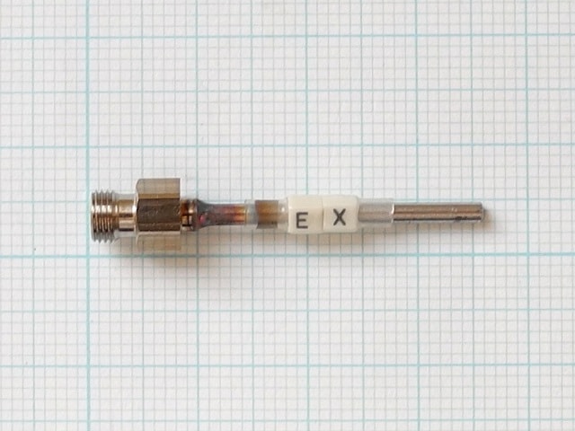
Step 5
Prepare the detector side of the column in the same way.
Normally, a nut with slit is used on the detector side, therefore, fix only the graphite ferrule with the Graphite jig (⑨). (If analyses are performed with column temperature set at more than 350 °C, thermal capacity may need to be reduced by using a small nut without slit, which is the same as the injection port side.)
The position where the graphite ferrule is fixed depends on the detector to be used.
Fix the graphite ferrule with the adjuster for each detector.
GC-2030
Detector |
Position |
Note |
|---|---|---|
FID |
72 mm |
When using metal capillary, 7 to 8 mm shorter. |
FID (When using Jetanizer) |
45 mm |
|
TCD |
50 mm |
|
FPD |
82 mm |
|
FTD |
69 mm |
When using metal capillary, 2 to 3 mm shorter. |
BID |
74 mm |
|
ECD(Flow path A)* Column flow rate is less than 2 mL/min |
43 mm |
Graphite ferrule jig, ECD_43mm
P/N 221-48610-07
is used. |
ECD(Flow path A)* Column flow rate is more than 10 mL/min |
38 mm |
When the column flow rate is 2 mL/min or more, make the length of the inserted column shorter than 43 mm to improve the durability of ECD cell (Example: when the column flow rate is 2 to 10 mL/min, 41 mm). Adjust the length of the inserted column because optimal length depends on analytical settings and the sample.If you want to adjust the column insertion length other than 43mm, use the graphite ferrule jig, ECD_43mm
P/N 221-48610-07
to fix the ferrule, then shift the position of the ferrule to adjust. |
ECD(Flow path B)* |
32mm |
Graphite ferrule jig, ECD_32mm
P/N 221-48610-04
is used. |
*Method for distinguishing the different ECD flow paths
ECD-2010 Exceed column insertion length differs depending on the flow path.
Refer to ECD-2010 Exceed
Method for distinguishing the different ECD flow paths
to determine the flow path.
GC-2050
Detector |
Position |
Note |
|---|---|---|
FID |
72 mm |
When using metal capillary, 7 to 8 mm shorter. |
FID (When using Jetanizer) |
45 mm |
|
FPD |
82 mm |
|
ECD |
32mm |
Graphite ferrule jig, ECD_32mm
P/N 221-48610-04
is used. |
STCD |
68mm |
Step 6
Pull the column oven door latch toward you to open the column oven door.
Step 7
Hang the column on the column hanger.
Step 8
Insert the column into the injection inlet.
Step 9
Turn the nut clockwise by hand to tighten it.
Step 10
Tighten it about 1/2 turn with a 6×8 spanner (②).
Step 11
Insert the column also on the detector side.
Step 12
Thread a nut (with slit) (⑥), and turn the nut clockwise by hand to tighten it.
Step 13
Tighten it about 1/2 turn with a 10×12 spanner (①).
Step 14
Close the column oven door.
Step 15
Start the GC.