![]()
Maintenance works must only be undertaken after the temperature of each part has been lowered to less than 50 deg.C.
Place any detached items on a clean sheet or tray. Do not lose or contaminate these items.
Undertake the works using the appropriate tools. Any dirt on the tools being used must be wiped off in advance using gauze etc. dipped in acetone.
10x12 wrench (standard accessory), 6x8 wrench (standard accessory), capillary cutter (option, Part No. 221-50595-91)
1 |
Shutdown the system and stop the gas supply for detectors. |
|
2 |
|
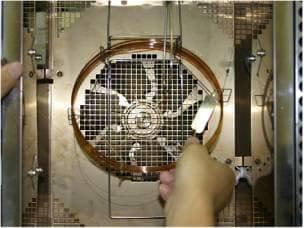
Pull the lever on the left hand side of the door to open the column oven. |
3 |
No make-up line type With make-up
line type |
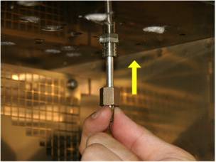
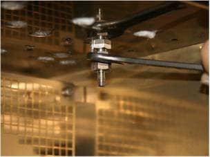
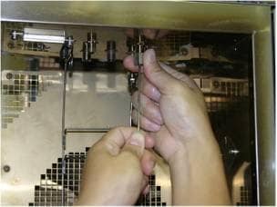
Fit the capillary adapter to the DET side and tighten it with a wrench. (Two types of capillary adaptors are available: ones with and without a makeup gas branch line.)
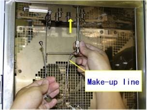
For the type with makeup gas line, tighten the capillary adapter and then connect the makeup gas line to the injection port.
Note: For the system configuration that allows for the use of both the packed column and the capillary column, use the AFC for the packed column, which is not used for the capillary analysis, for sending makeup gas. In this case, you need to change the dual AFC setting to the makeup gas mode. Supplying makeup gas from the injection port using the capillary adaptor with make-up line type may have an adverse effect on analysis, such as an increase in noise due to the effects of organic substances from the graphite ferrule or due to contamination inside the injection port, and may prevent the system from fulfilling its specifications. Therefore please refer to the Operation Manual before using it. |
4 |
|
Pass the capillary column entrance side through a hexagon cap nut and the graphite ferrule. Cap nut 221-16325-01 Graphite ferrule 0.5mm 221-32126-05 Graphite ferrule 0.8mm 221-32126-08
|
5 |
|
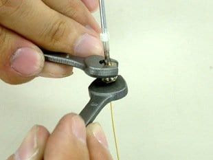
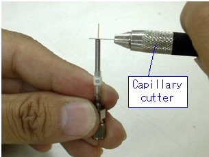
Fix the graphite ferrule provisionally using the graphite fixing jig. When doing so, let the capillary column protrude about 10mm from the graphite fixing jig, and cut the column using a capillary cutter etc. at the tip of the fixing jig. If the fixing jig for the SPL is used, the position will be fixed at 34mm from the column tip. Capillary cutter 221-50595-91
Caution: Change the graphite fixing position to 15mm if intending to conduct splitless analysis using a wide-bore column of 0.53mm inner diameter.
|
6 |
Using the fixing jig, fix the graphite ferrule on the detector side of the capillary column as well. Since, normally, a locking nut is used, a cap nut need not be used ahead of the graphite ferrule (if analyses are conducted at column temperatures over 350 deg.C, it may be a good thing to reduce the thermal capacity by using a small cap nut in the same way as the entrance side). For the FID/FTD-2014 99mm (make it 2 to 3mm shorter if a metal
capillary column is used.) Remove the fixing jig once the position of the graphite ferrule is set.
Note:
|
|
7 |
|
Hang the column on the column hanger. |
8 |
|
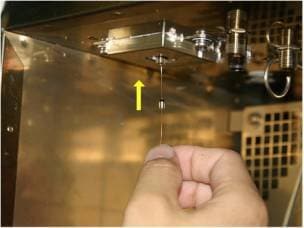
Insert the column into the sample injection port from the column oven side. |
9 |
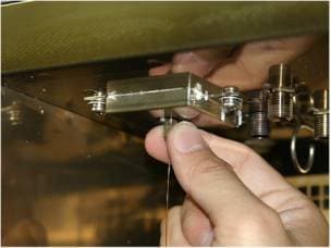
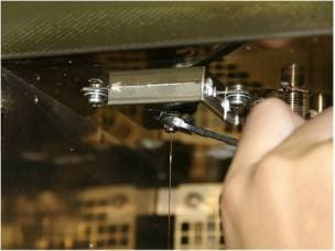
|
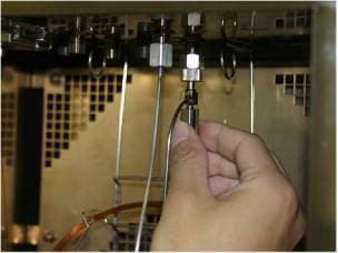
After tightening the nut by hand, fix in place by turning the nut another half-turn using the wrench.
|
10 |
|
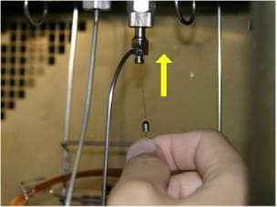
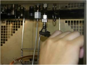
In the same way, insert the column into the detector from the column oven side, and after turning the locking nut by hand to tighten it, fix it by tightening it about a half-turn further with the wrench. |
11 |
Close the column oven door and start up the system. |
|
Maintenance Top ; GC-2014 Main ; GC-2014 Detector ; GC-2014 Sample Injection Port ; GC-2014 Column Oven