![]()
Maintenance works must only be undertaken after the temperature of each part has been lowered to less than 50 deg.C.
Place any detached items on a clean sheet or tray. Do not lose or contaminate these items.
Undertake the works using the appropriate tools. Any dirt on the tools being used must be wiped off in advance using gauze etc. dipped in acetone.
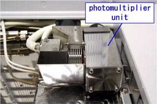
Do not remove the photomultiplier unit while the system is operating or the FPD is on as this may damage the photomultiplier.
Phillips screwdriver
|
1 |
Shutdown the system. |
|
|
2 |
|
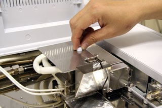
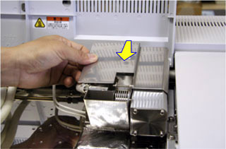
Remove the knurled screw on the top.
|
|
3 |
|
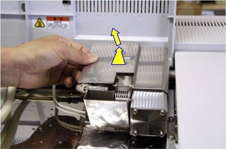
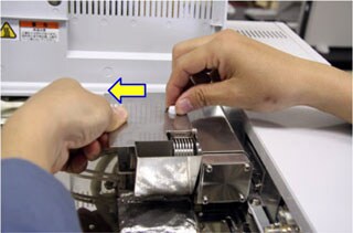
Slide the FPD top cover borad then remove it.
|
|
4 |
|
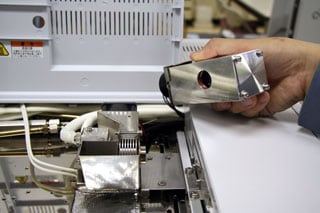
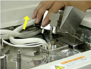
Slowly pull the photomultiplier unit out horizontally to remove it. Cover the photomultiplier receiver with aluminum foil etc. to avoid exposure to intense light.
|
|
5 |
|
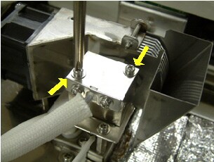
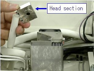
Remove the 2 screws and remove the head section. |
|
6 |
|
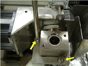
Remove the 2 body unit setscrews and remove the body section fixing plate.
|
|
7 |
|
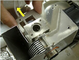
Pull the body section out upwards. |
|
8 |
|
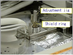
Fit the shield ring adjustment jig inside the shield ring. Rotate the shield ring to adjust its height. The height will be 2.0mm if the top of the shield ring is aligned with the groove on the bottom (the spacing between grooves is 1mm). Adjust to 2mm when using the SPL injection port, and to 4mm in the case of the WBI injection port.
|
|
9 |
Remove the shield ring adjustment jig and insert the body unit. |
|
|
10 |
Insert the body section fixing plate and fix it with the 2 screws. |
|
|
11 |
Put back the head section and fix it with the 2 screws. |
|
|
12 |
Slowly attach the photomultiplier unit. |
|
|
13 |
|
Put back the top cover board and slide it to adjust the screw position. |
|
14 |
|
Tighten the knurled screw with pulling the board to the left so that it fits on the photomultiplier unit.
|
|
15 |
Start up the system. |
|
|
Note: |
||
Maintenance Top ; GC-2010 Main ; GC-2010 Detector ; GC-2010 Sample Injection Port ; GC-2010 Column Oven