![]()
Maintenance works must only be undertaken after the temperature of each part has been lowered to less than 50 deg.C.
Place any detached items on a clean sheet or tray. Do not lose or contaminate these items.
Undertake the works using the appropriate tools. Any dirt on the tools being used must be wiped off in advance using gauze etc. dipped in acetone.
6x8 wrenchs (standard accessory)
1 |
Shutdown the system. |
|
2 |
|
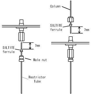
The analytical column can be installed on the upper side of the back flush device with a SILTITE ferrule (metal ferrule) and a cap nut. Pass the column through the cap nut and SILTITE ferrule, insert it from upper side until the column top touches the bottom, then tighten the nut with your hand.
There are three types of SILTITE ferrule, an appropriate one must be used to fit the column diameter. For example, for the 0.25 mmID capillary column, use SILTITE, ferrule 0.25 (SSOT-221-72563-04). SILTITE, ferrule 0.25 : SSOT-221-72563-04
(ferrule 0.4 mmID) |
3 |
|
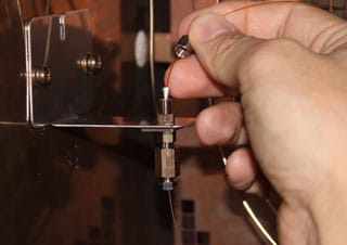
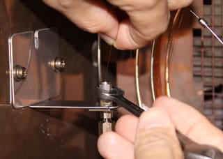
Hold
the column, tighten the nut with the wrench. Because each column is slightly different in outside diameter, the tightning angle also differs. Normally it is in 90 - 120 degree to fix the column. The SILTITE ferrule can not be reused, and note that it might cause gas leak if you tighten it too much. |
4 |
Install the injection port side of the column with a graphite ferrule using the same procedure as standard column installation. GC-2010 Installing the Capillary Column
|
|
5 |
|
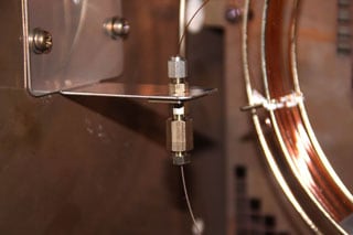
After installing the column, start the carrier gas flow (set 300 kPa on APC), then check gas leakage at all conjunctions with a helium detector or leak detector fluid (ex. Snoop). |
Maintenance Top ; GC-2010 Main ; Back Flush ; GC-2010 Column Oven ; GC-2010 Detector ; GC-2010 Sample Injection Port